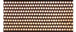
 Lead-fiber structure (NIM fig. 2.128)
Lead-fiber structure (NIM fig. 2.128)
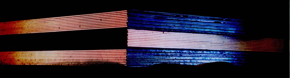 Three superlayers (NIM fig. 2.129)
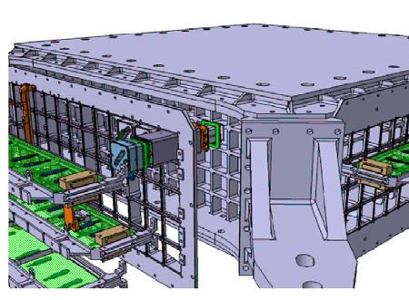
 Exploded view of mechanics (NIM fig. 2.130)
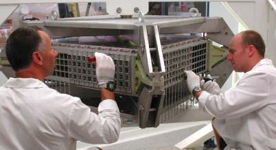 Mechanics and assembly (NIM fig. 2.131)
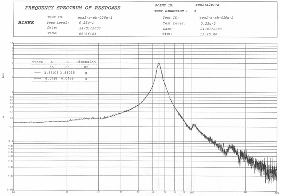 Vibration sine sweep response (NIM fig. 2.132)
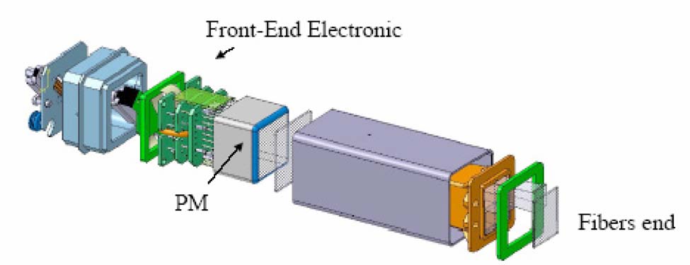 PMT and light collection system (NIM fig. 2.133)
 Response to 10 GeV electrons (NIM fig. 2.135)
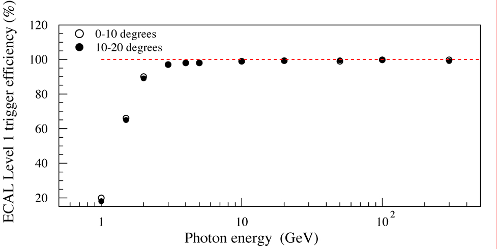 Trigger efficiency afo photon energy (NIM fig. 2.136)
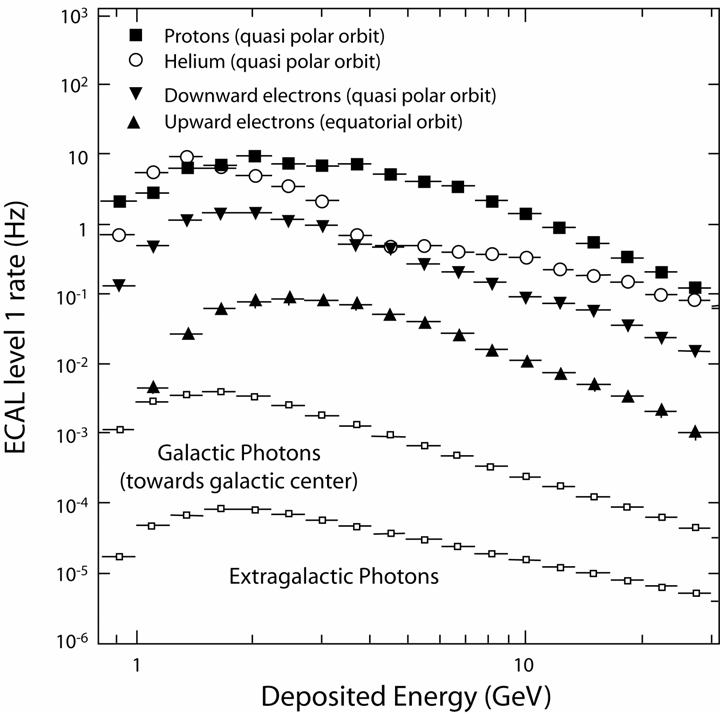 ECAL trigger background and photon rates (NIM fig. 2.137)
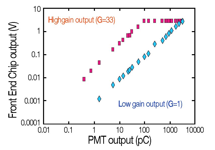 Front-end chip response (NIM fig. 2.138)
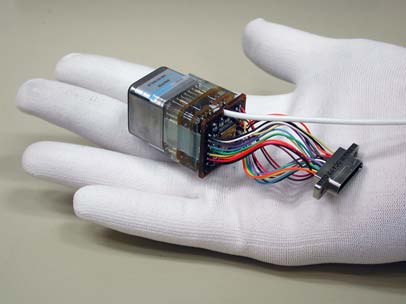
 PMT with potted HV divider and front-end electronics (NIM fig. 2.139)
 EDR2 schematics (NIM fig. 2.140)
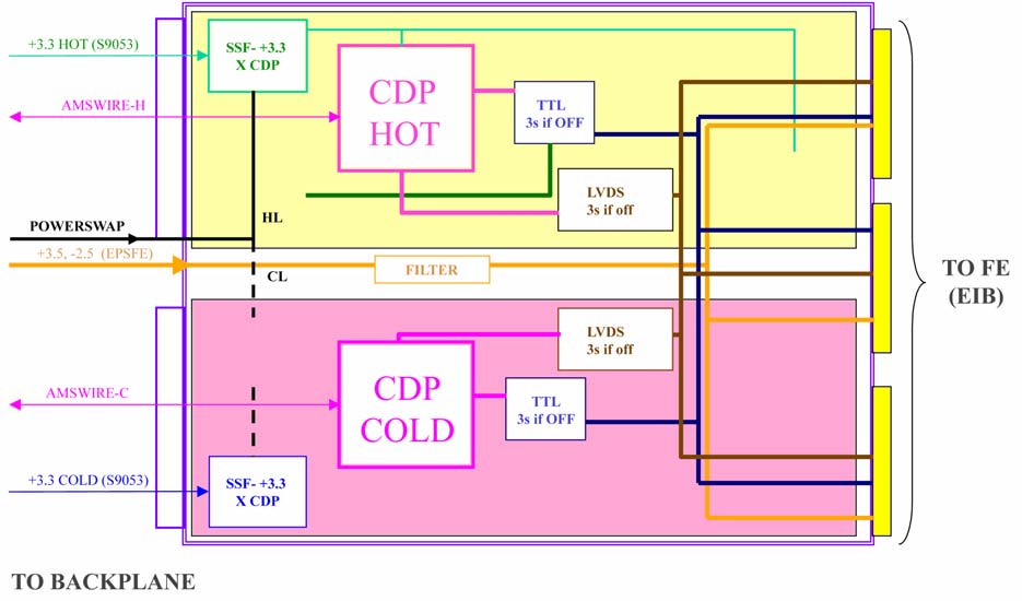
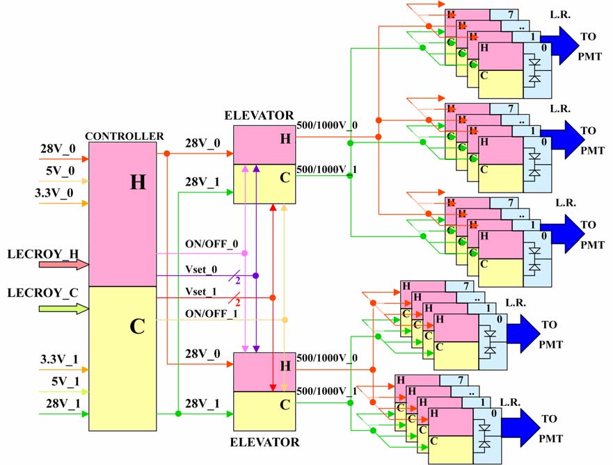
 Slow control architecture (NIM fig. 2.141)
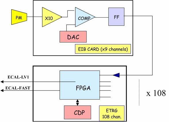 ECAL trigger circuit (NIM fig. 2.142)
 Trigger firmware timing simulation (NIM fig. 2.143)
 HV brick schematics (NIM fig. 2.144)
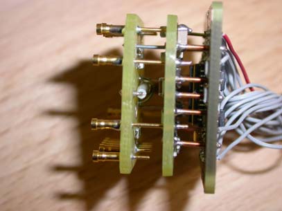
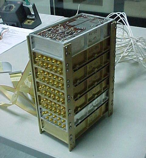 HV brick prototype (NIM fig. 2.145)
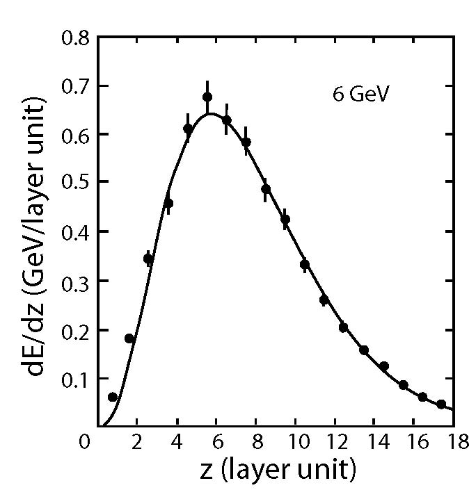
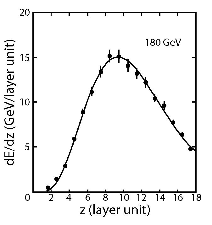 Typical shower profiles (NIM fig. 2.146)
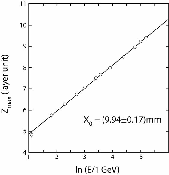 Position of shower max vs energy (NIM fig. 2.147)
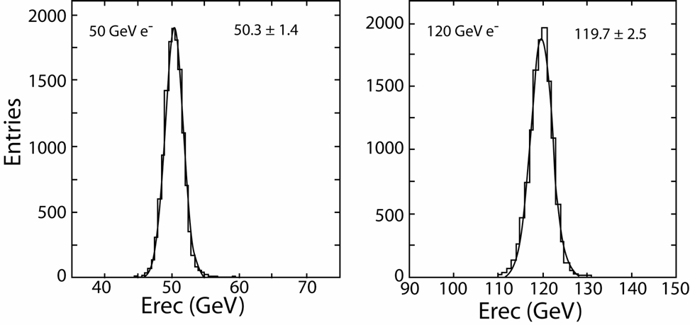 Typical energy measurement for electrons (NIM fig. 2.148)
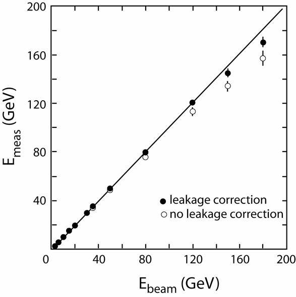 Leakage corrected linearity (NIM fig. 2.149)
 Energy resolution (NIM fig. 2.150)
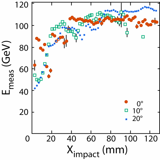 Measured energy afo impact position (NIM fig. 2.151)
 Angular resolution for 50 GeV electrons (NIM fig. 2.152)
 Angular resolution afo electron energy (NIM fig. 2.153)
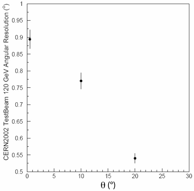 Angular resolution afo incident angle (120 GeV e) (NIM fig. 2.154)
 Misidentification probability afo electron efficiency (NIM fig. 2.155)
 Light guide (NIM fig. 2.134)