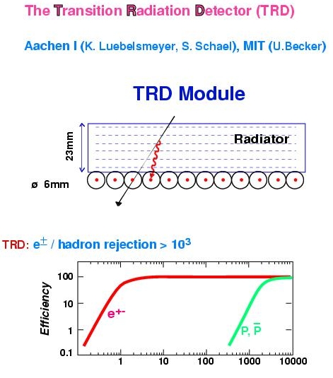
 TRD principle
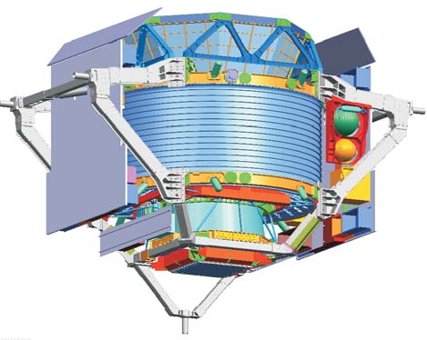
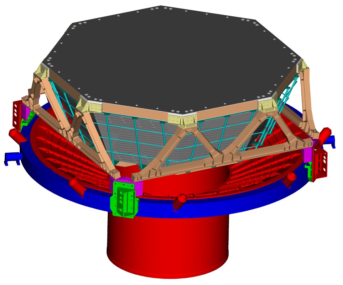 TRD on vacuum case (NIM fig. 2.25)
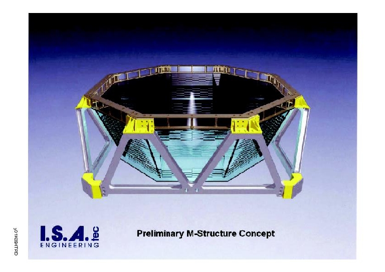
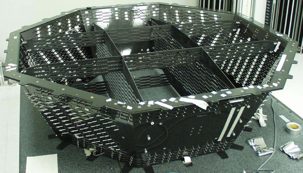 Octagon structure (NIM fig. 2.27)
 Modal analysis (NIM fig. 2.28)
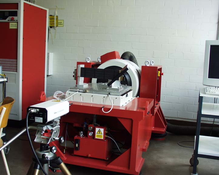 Straw tube vibration test (NIM fig. 2.29)
 Straw tube module (NIM fig. 2.30)
 Straw tube computer tomography (NIM fig. 2.31)
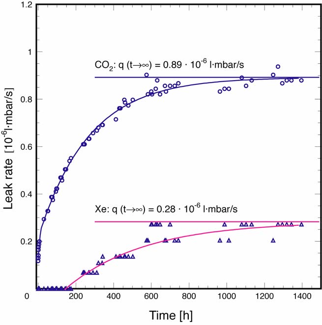 Straw tube leak rate (NIM fig. 2.32)
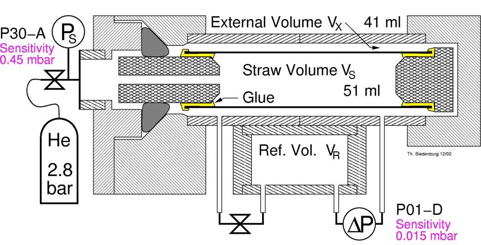 Straw tube test stand (NIM fig. 2.33)
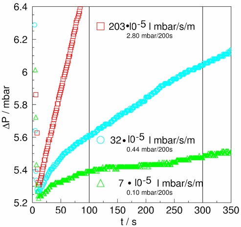 Straw tube leak rate example (NIM fig. 2.35)
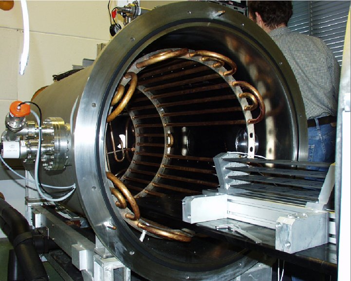 TRD module thermovacuum test (NIM fig. 2.38)
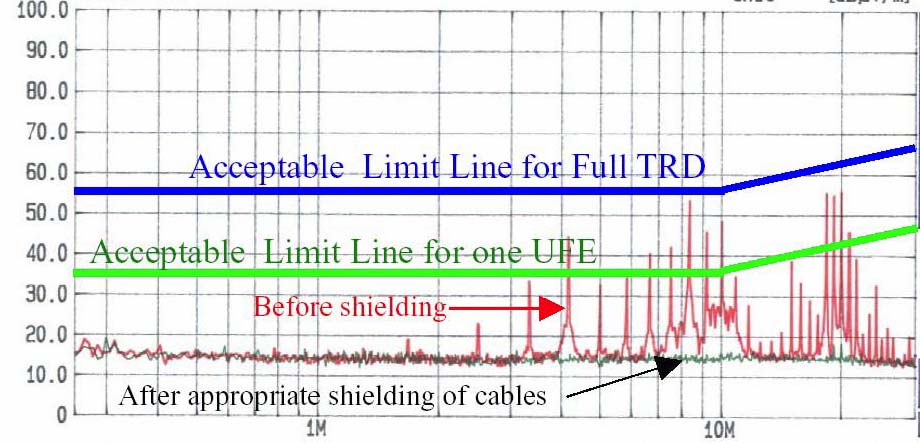 UFE EMI test result (NIM fig. 2.41)
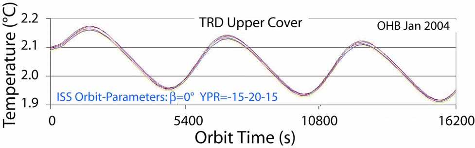 TRD simulated temperature (NIM fig. 2.43)
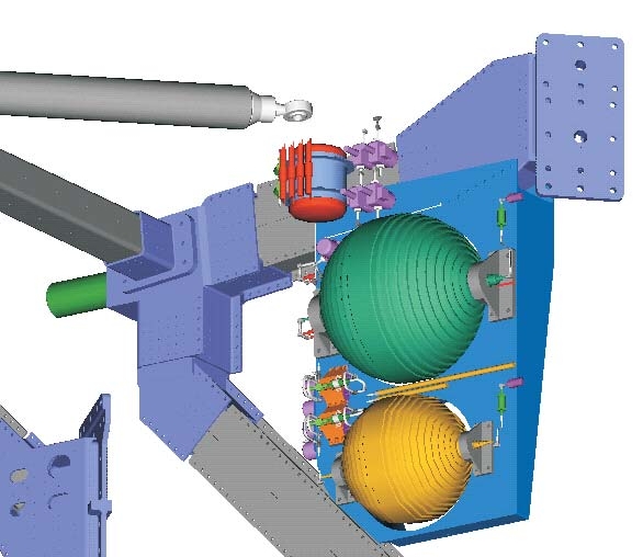 Gas system accommodation detail (NIM fig. 2.45)
 Gas system electronics boards (NIM fig. 2.49)
 Box S engineering model (NIM fig. 2.50)
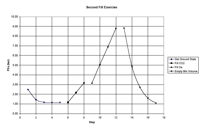 Box S fill cycle (NIM fig. 2.52)
 Temperature distribution for valve failure (NIM fig. 2.53)

 Box C engineering model(NIM fig. 2.54)
 Prototype with 20 layers (NIM fig. 2.55)
 Prototype pulse height distribution (NIM fig. 2.56)
 TRD proton rejection factor (NIM fig. 2.57)
 TRD support concept
 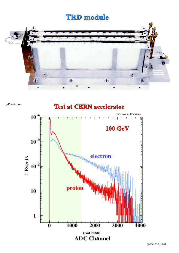 TRD beam test
  UFE board (NIM fig. 2.40)