Detector Development - Liquid Argon Calorimeter
(Français/English)For liquid argon calorimeters as for other detectors, the Read-Out Driver (ROD) is the central element of back-end electronics. In this field, the University of Geneva has contributed and still contributes to the following activities:
Development of the Read-Out Driver
The Read-Out Driver obbeys the 9U VME64x protocol. As can be seen, it is composed of a motherboard and 4 mezzanine boards. The Printed Circuit Board (PCB) of the motherboard has been designed by the DPNC group, while mezzanines have been developed by LAPP and Nevis groups. Almost one year has been necessary to produce the 192 ROD modules of the liquid argon calorimeter. A brief explanation of how a ROD module works is given in the following. On the picture, data travel from left to right:
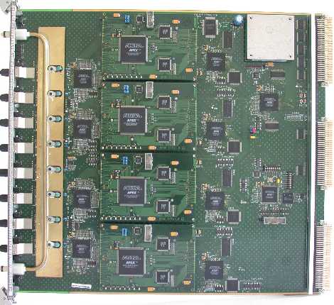
- 8 receivers convert optical signals sent by front end boards into electrical signals
- For each channel, a chip deserializes incoming data; these chips are water-cooled to ensure optimal performance (the copper radiator is clearly visible)
- Channels are routed in pairs to 4 Field-Programmable Gate Arrays (FPGA) which synchronize data with respect to the LHC clock signal
- Data are sent to the 4 mezzanine boards, the Processing Units (PU). Each PU is equipped with 2 Digital Signal Processors (DSP) which execute the physics algorithm, i.e. compute the energy, time and quality of the ionization pulse. It also receives Timing Trigger and Control (TTC) information from a dedicated FPGA (bunch crossing and event numbers, trigger type)
- 4 controllers read and format the DSP output data
- Event fragments are serialized, and finally come out of the ROD via the VME interface (white connectors)
Validation and repair of ROD boards
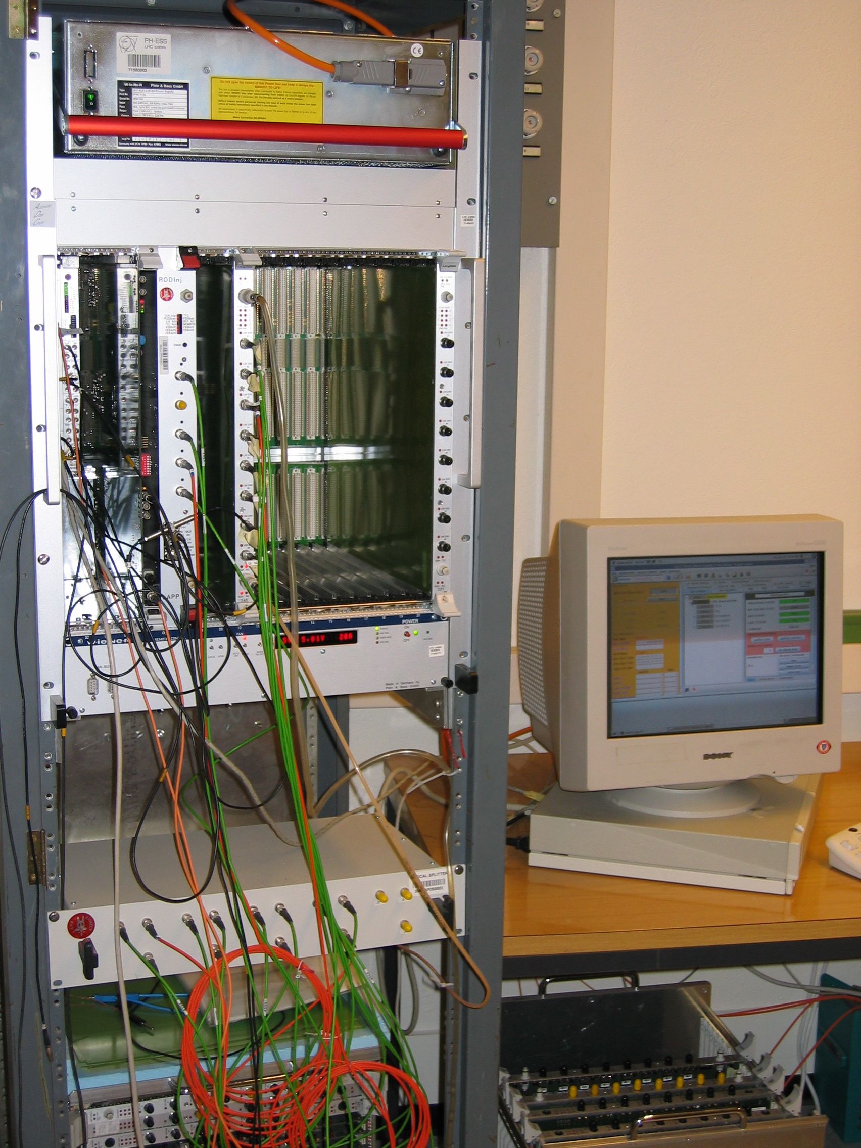 Before being installed in the ATLAS cavern dedicated to back-end electronics, each ROD module has been validated with a
test bench.
The setup shown on the right reproduces a part of the data acquisition chain. Front end boards are replaced with an injector module which emulates data.
As the injector only has 5 output channels, an optical splitter is used to feed the 8 input channels of the ROD board.
Level 1 Accepts (L1A) and TTC signals are produced by the injector as well.
A test consists in a series of write/read cycles, and allows to verify the behavior of every component of the ROD board at each step of data processing.
Tests are performed in the same software environment as for real data taking.
The validation of ROD modules came to completion by the end of 2005.
The test bench is now used to indentify problems in faulty boards.
Maintenance of ROD racks
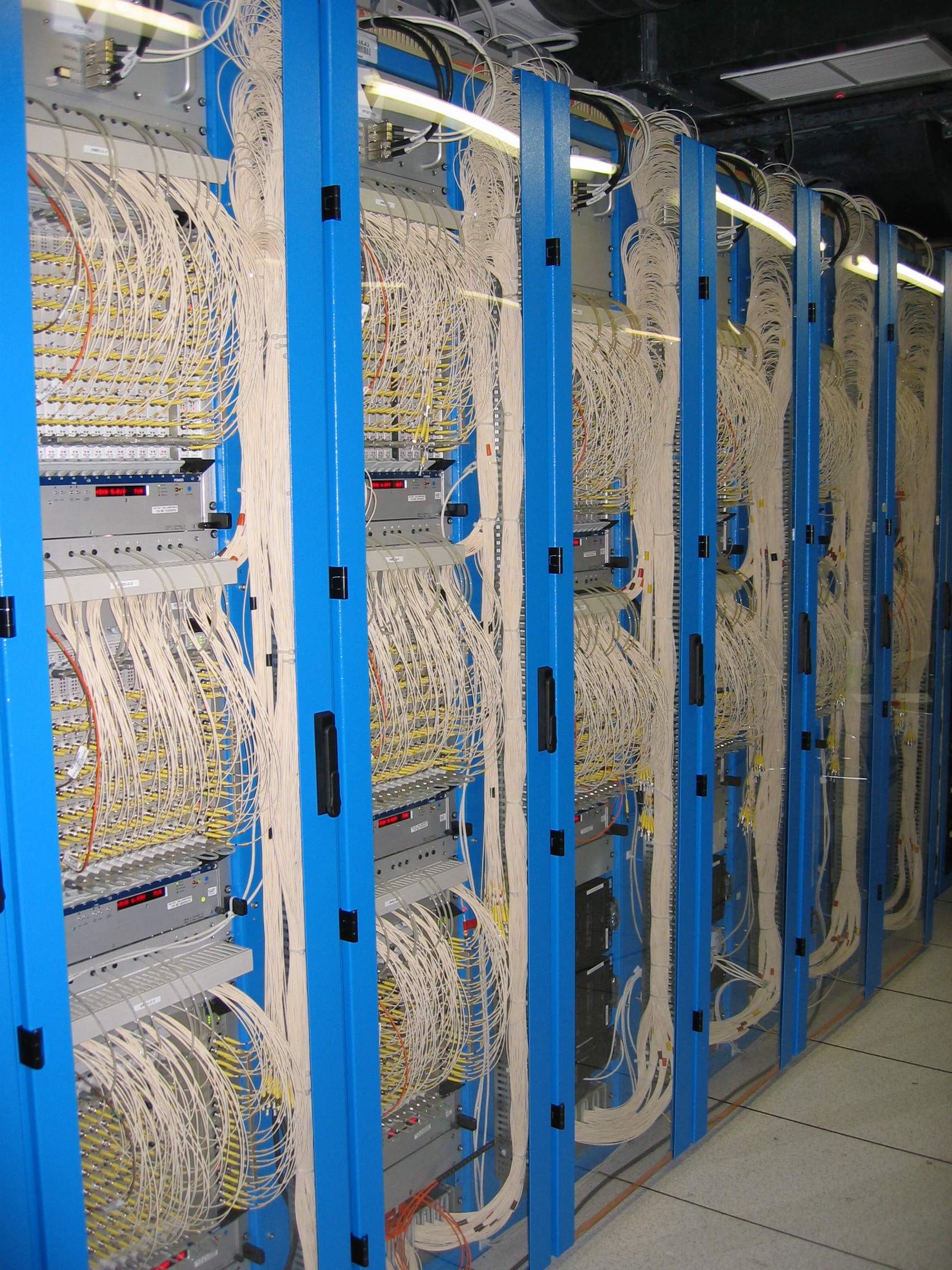
The Geneva group is in charge of ROD racks operation. A rack is composed of two or three crates, each of which containing:
- a CPU controlling the crate via a VME interface
- between 6 and 14 ROD modules, depending on the calorimeter (electromagnetic barrel, electromagnetic end-cap, hadronic end-cap or forward calorimeter)
- one Transition Module (TM) per ROD module, which sends output data to the Read-Out Subsystem (ROS) through optical fibers
- a TTC and Busy Module (TBM), which collects the "busy" signal emitted by ROD boards when buffers are almost full, indicating that incoming data cannot be accepted temporarily
- 2 SPAC Master modules, which configure front end boards
- a fan tray, which ensures air cooling of all components mentionned above
- a cooling drawer, which maintains specific chips of ROD boards below 35°C thanks to circulating water
- a low voltage water-cooled power supply, delivering ~ 75 A
- a Detector Control System (DCS) interface, which monitors voltages, currents and temperatures in the rack, and receives information from the cooling station
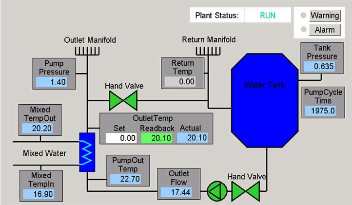
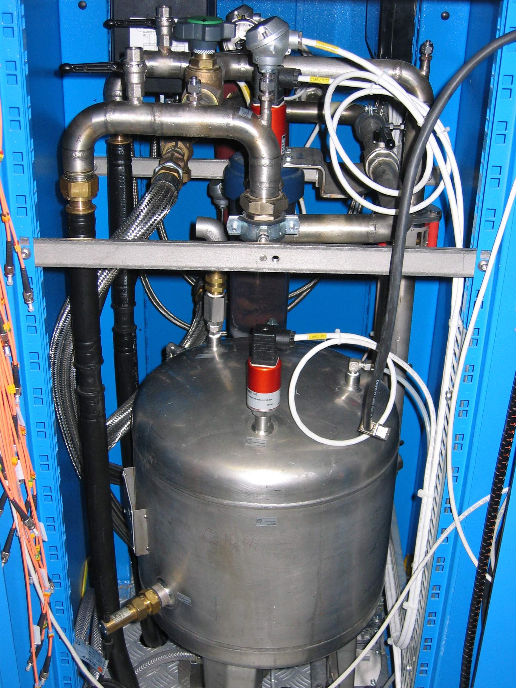
Below is displayed a diagram of the water-cooling station, and a view of the water tank. A vacuum pump is connected to the hydraulic system such that
the water pressure remains below the atmospheric pressure all along the circuit. Thus, water does not leak on boards in case of problem.
The cooling drawers are connected in parallel between the outlet and return manifolds.
The University of Geneva has played a leading role in the design of these drawers, which have to resist to mechanical stress and corrosion.
Last modified: 2009/05/05