SEQUENCE OF WORK ON SCT BARRELS ep27/11/98
DRAFT
- Cylinder + flange manufacture.
- QA tests + metrology
- Dry the cylinder (avoid vacuum) (this define T0 with cylinder completely dry)
- Thermal cycling to stabilise structure.
- CTE tests? (do we really need them on cylinder / or flat samples?)
- Mount tooling rings (TR) and tooling flanges (TF) to cylinder (concentric with mean dia obtained from metrology) (see 252325P4H)
- Bond inserts with adequate tooling, use the TR & TF as reference
- Machine inserts surface and precise holes, using TR & TF as reference.
- Metrology (TR & TF as ref?)
- Transport in container to trial assy lab (support from TF, spindle)
- Provisional acceptance.
- Perform trial assembly with other cylinders. This operation would require the TF to be dismounted except for cylinder 3. The trial assembly is also important to validate the assembly method and tooling.
- Disassemble the 4 cylinders, remount TF on each.
- Transport in container to module assy lab.
- Install cylinder in assembly station, (supported by spindle).
- Mount brackets.
- Evtl. Metrology?
- Mount cooling pipes, manifolds and test for leaks
- Install services support extensions (SSE)
- Mount cable harnesses
- Mount DCS components
- Mount tested modules and check connections.
- Test complete barrel (incl thermal cycling)
- Barrel ready
- Install complete SCT barrel in container (support with spindle?)
- Transport complete barrel to CERN
- Remove barrel from container and install on temporary support with adequate handling points, remove spindle (cyl. Protection!) (see 252346P4H)
- Reception test on Barrel
- Prepare Barrel for assembly
- Prepare cradle (equipped with similar rails as the ones fixed in TRT inner shell) and assembly wagon. (see 252356P4H)
- Mount thermal enclosure in cradle, directly supported from rail. Leak test
- Introduce the assembly wagon into Barrel 6 (see 252347P4H)
- Transfer B6 from temporary support to assembly wagon (see 252348P4H)
- Introduce B6 into thermal enclosure, using the assembly wagon, adjust position. (see 252349P4H)
- Mount B6 bearings, transfer barrel weight to rails
- Remove assembly wagon and TF of barrel 6
- Evtl. Seal B6 bearings where they pass through the thermal enclosure
- Repeat operations 27,28, 29 and 32 for barrel 5. (see 252350P4H)
- Introduce barrel 5 into barrel 6, using assembly wagon, adjust position (see 252351P4H)
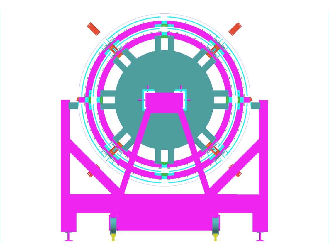
- Mount interlinks, transfer barrel 5 weight to the interlinks. (see finbarrel2.jpg)
- Remove assembly wagon and TF of barrel 5.
- Repeat operations 27,28, 29 and 32 for barrel 4. (see 252352P4H)
- Introduce barrel 4 into barrel 5, using assembly wagon, adjust position (see 252353P4H)
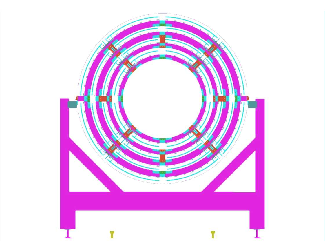
- Mount interlinks, transfer barrel 4 weight to interlinks. (see finbarrel4.jpg)
- Remove assembly wagon and TF of barrel 4.
- Repeat operations 27,28, 29 and 32 for barrel 3. (see 252354P4H)
- Introduce barrel 3 into barrel 4, using the assembly wagon, adjust position
- Mount interlinks, transfer barrel 3 weight to interlinks.
- Remove assembly wagon and TF of barrel 3. (see 252357P4H)
- Replace temporary interlinks with final ones (if necessary). (see finbarrel6.jpg)
At this stage, the 4 barrels are linked together in the right relative position. Their services are still supported on the extensions attached to the rings fixed at each cylinder end.
- Mount thermal enclosure bulkhead (TEB) (TEB has to be compatible with barrel 6 SSE)
- Mount sealing between thermal enclosure and interlinks.
- Prepare the temporary radial cable support (TRCS)
- Transfer cables from barrel 6 to TRCS, arrange correct position in TEB.
- Remove SSE and TR from barrel 6
- Transfer cables from barrel 5 to TRCS, arrange correct position in TEB.
- Remove SSE and TR from barrel 5
- Transfer cables from barrel 4 to TRCS, arrange correct position in TEB.
- Remove SSE and TR from barrel 4
- Transfer cables from barrel 3 to TRCS, arrange correct position in TEB.
- Remove SSE and TR from barrel 3
- Apply sealant between cables and TEB.
- Install the 32 I & O pipes from barrel end to TEB
- Leak test all cooling circuits up to TEB.
- Mount thermal enclosure lid (TEL)
- Evtl. SCT Barrel ready for X ray survey (cfrp tube guiding the Xray head to be inserted inside the barrel 3 and adequately supported, from the cradle?)
- Mount the Services Support Wagons (SSW) on cradle rails
- Transfer services from TRCS to SSW and x-check outside diameter
- Dismount TRCS
- Final check before insertion inside the TRT
- Move SCT barrel in cradle in front of TRT
- Insert SCT barrel into TRT. (short rail extension are needed on the opposite end, to support the SSW)
- Unfold services from SSW to "final position"
- Remove the SSW
- Evtl SCT Barrel ready for X ray survey (cfrp tube guiding the Xray head to be inserted inside the barrel 3 and adequately supported, from the cradle?)
- Remove the TEL
- Prepare rails and tooling for the Pixel introduction
- Introduce Pixel detector
- Unfold pixel cable and route them on barrel end face seal at TEB
- Remove the temporary rails
- Mount the cooling pipes from Pixel to TEB
- Close the TEL
- Final test of ID Barrel prior installation in the pit
List of abbreviations:
B4 Barrel 4
TF Tooling Flange
TR Tooling Ring
SSE Services Support Extension
SSW Services Support Wagon
TEB Thermal Enclosure Bulkhead
TEL Thermal Enclosure Lid
TRCS Temporary Radial Cable Support